An Affordable PDN Analyzer
This particular piece of hardware is a result of the decoupling / parasitic inductance deep dive I did last year (2024).
Details
To verify the AC decoupling simulations I was running, and get more of a feel for all of the effects at play, I needed a way to measure tiny AC impedances (preferably below milliohms), up to at least the frequency where one minor inductance dominates (about 10MHz), with DC biases applied of ideally at least 12 volts.
The best purchasable method I found to do these tiny impedance measurements was using a particular type of NanoVNA (that runs from 50kHz onwards) with Joe Smith’s now unmaintained version of his NanoVNA windows software. This gave meaningful results! The combination is however some work to set up, buggy, doesn’t have the best UI, has the VNA’s impedance measurement’s typical problem of having ground loop issues (that would require expensive or custom wound transformers to mitigate), and only runs from 50kHz onwards (and thus missing a big range of interest for these types of measurements).
I also tried heavily modifying the circuity of my Analog Discovery 2. In its default configuration it does impedance measurements beautifully, but only down to about an ohm or so. With 20x extra gain, a high current buffer instead of the original waveform buffer chip, and tiny twisted pairs soldered directly to the PCB, I was able to measure impedances down to the milliohm with decent accuracy. While the AD2’s UI is a blast to work with, the mechanical setup was a nightmare. The tiny enameled wires kept breaking, I’d need to get DC bias capacitors in there if I wanted to measure something powered one, and I’ve fried a component on the AD2’s circuit board more than once.
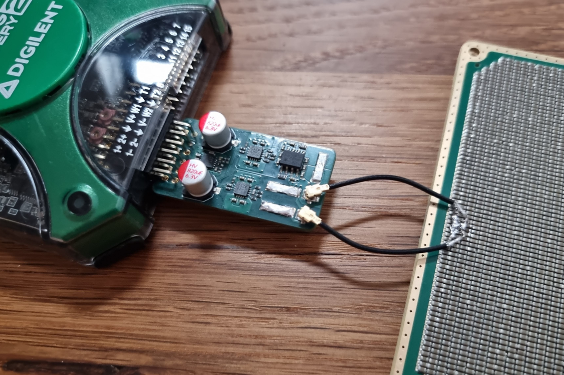
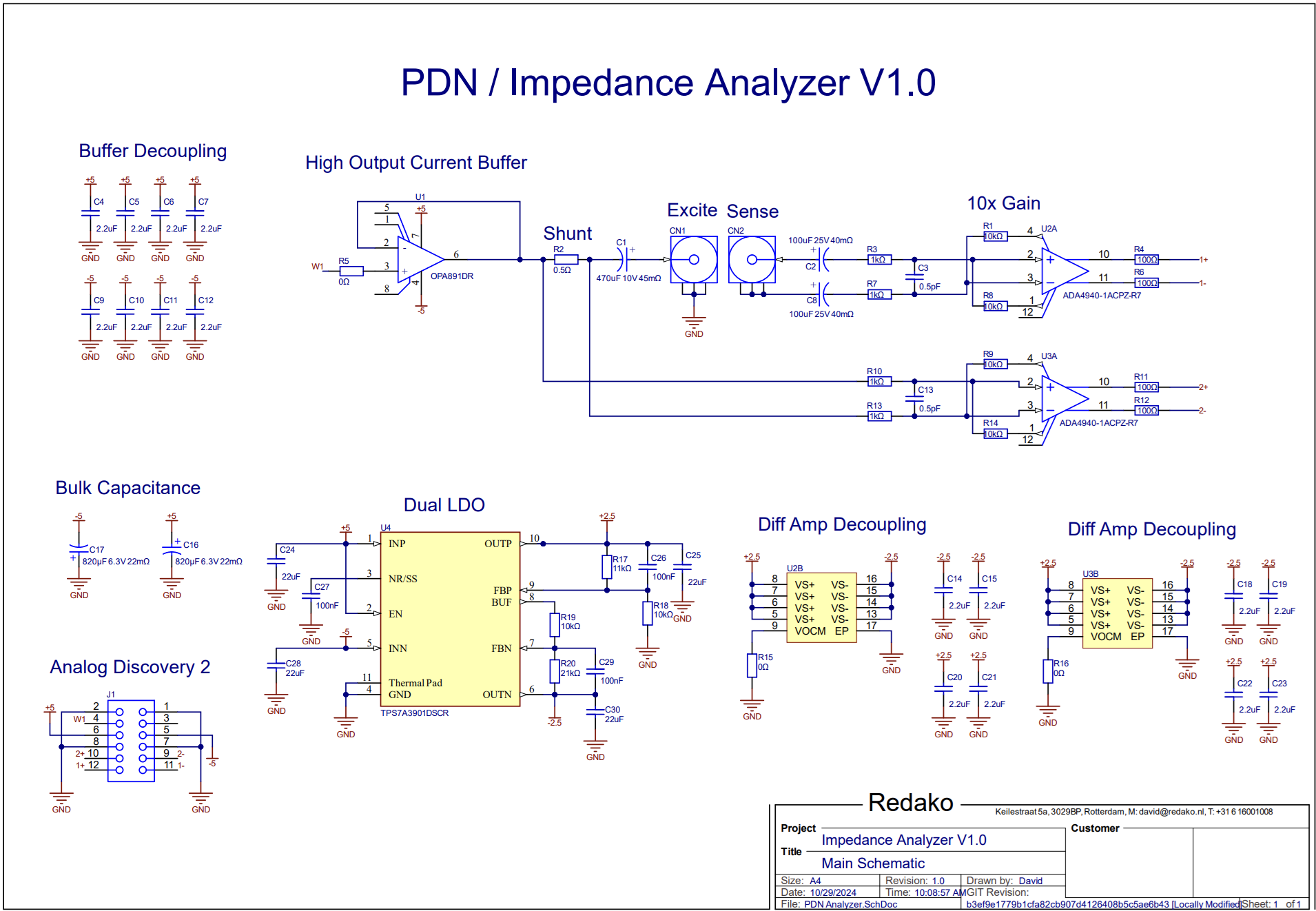
This lead me to design these! Analog Discovery 2/3 extension boards to do DC – 25MHz Power Delivery Network / Impedance analysis measurements. The final (and first) version measures impedance from 10kΩ all the way down to 100µΩ, with and without DC bias, on both powered and unpowered DUTs, basically doing a true 4 wire resistance measurement for AC impedances.
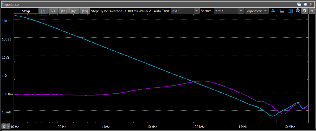
In the gallery below is a measurement screenshot of a Nucleo32 development board’s 3.3V rail. Both when it’s on, and when it’s off. When it’s off we only see the ceramic capacitors at play. One text book dip with a resonance frequency at 4MHz. When it’s on we also see the LDO supplying current with 100mΩ series resistance, which doesn’t really keep up from 10kHz onwards. At the 100kHz we see the ceramic capacitors joining in again, but with less effective capacitance than when it was off, due to the DC bias of 3.3V now applied to the capacitors.
For more information, schematics, and design files, check out the GitHub page.